First an overview about the impedance at mobile antennas.
A 2m long antenna on the car has got: ( without any loading-coil )
|
Band |
160m | 80m | 40m | 20m |
| Impedance | 0.06ohm -j3978ohm | 0.25ohm -j1922hm | 0.9ohm -j975ohm | 3.87 -j445 |
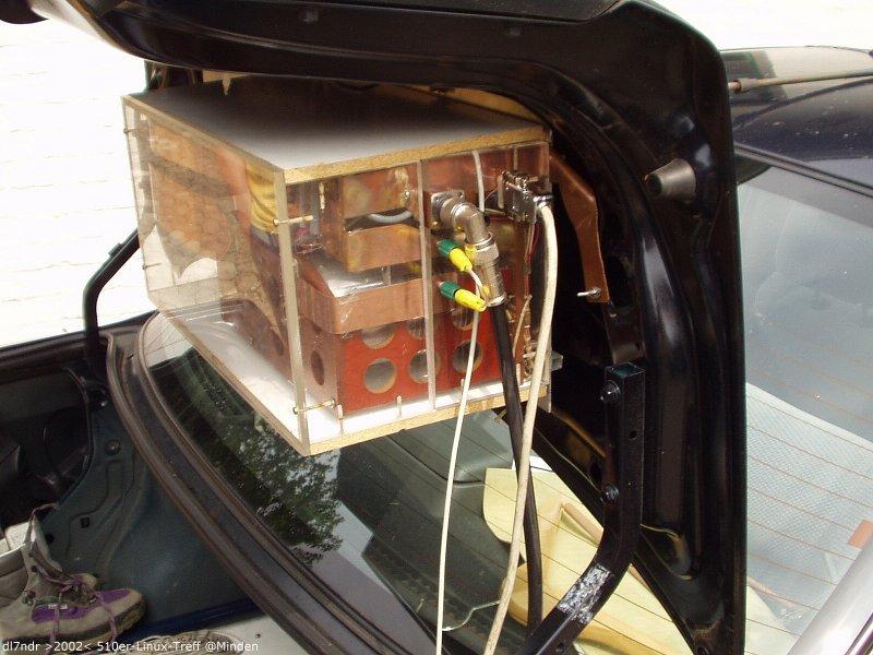
The first problem is to handle the impedance at the feedpoint. So it is necessary to have a matching-network on the feedpoint. A matching just at the tranceiver is not acceptable because of big loss on the transmission line. There are some possibilities to solve this. Mostly it is used the L-network. The advantage is, that the capacitors can be switched with relays because of the low voltage at this point and the variable inductor can be used to make the antenna resonant on the higher bands like 10m. The capacitor series used here is 50pF, 100pF, 200pF, 400pF, 800pF, 1600pF and the inductance is about 60uH.
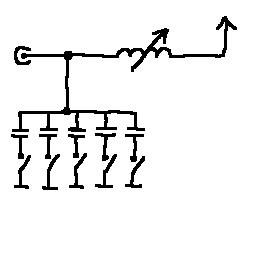
Feedpoint - matching - network
Furthermore it is necessary to have a loading-coil for the top-band, 160m, 80m and 40m. Keep in mind that the coil sould be desinged for the highest frequency at the band, i.e. 3.8mhz (US:4Mhz) or a little more because you have a second coil in the feedpoint - matching - network. The value can also be calculated quite simple: In order to make 10ohm -j2000ohm resonant, you need a coil having +j2000ohm. The corresponding L, i.e. for 3,8Mhz is then:
L = X / (2*Pi*f) = j2000 / (2 * 3,14 * 3 800 000) = 0,000 083 H = 83uH.
For each Band this may be:
| Band | 160m | 80m | 40m | 20m |
| Inductance for resonance | 4200ohm | 2070ohm | 1090ohm | 470ohm |
| L/uH | 361uH | 86uH | 24uH | 5.3uH |
| new impedance | 10ohm +j30ohm | 10ohm +j20ohm | 10ohm +j20ohm | 13ohm +j8ohm |
Antenna with coil has got a much higher resistance because of the coil-loss! Here a coil-loss for 9ohm is supposed.
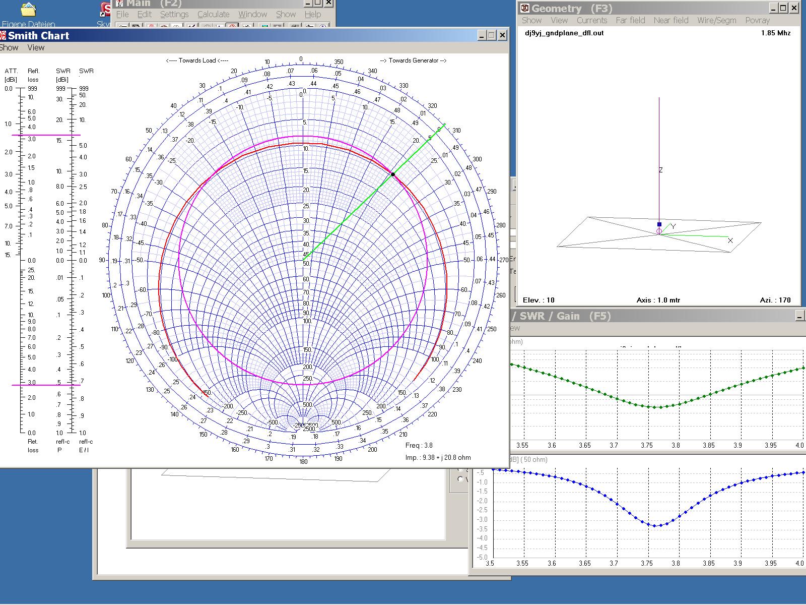
The new impedance is calculated with 4nec2, including the suggested coil-loss.
Impedance in smith-chart after loading-coil looks like this here for 80m
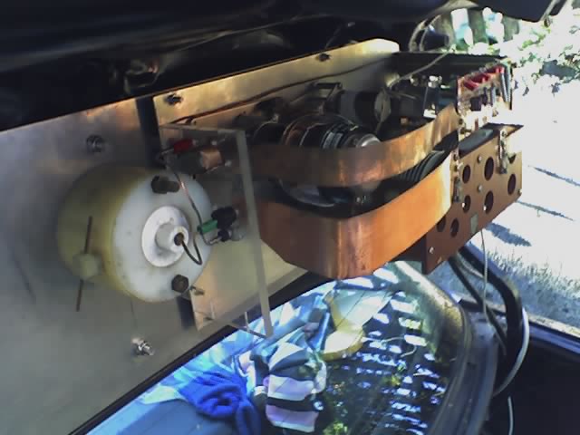
Pay attention to the coil-wires: The resistance at the loading-coil is low, so there is a lot of current and you sould have some distance between the wires because of extrusion of current. Otherwise you will lose efficiency.
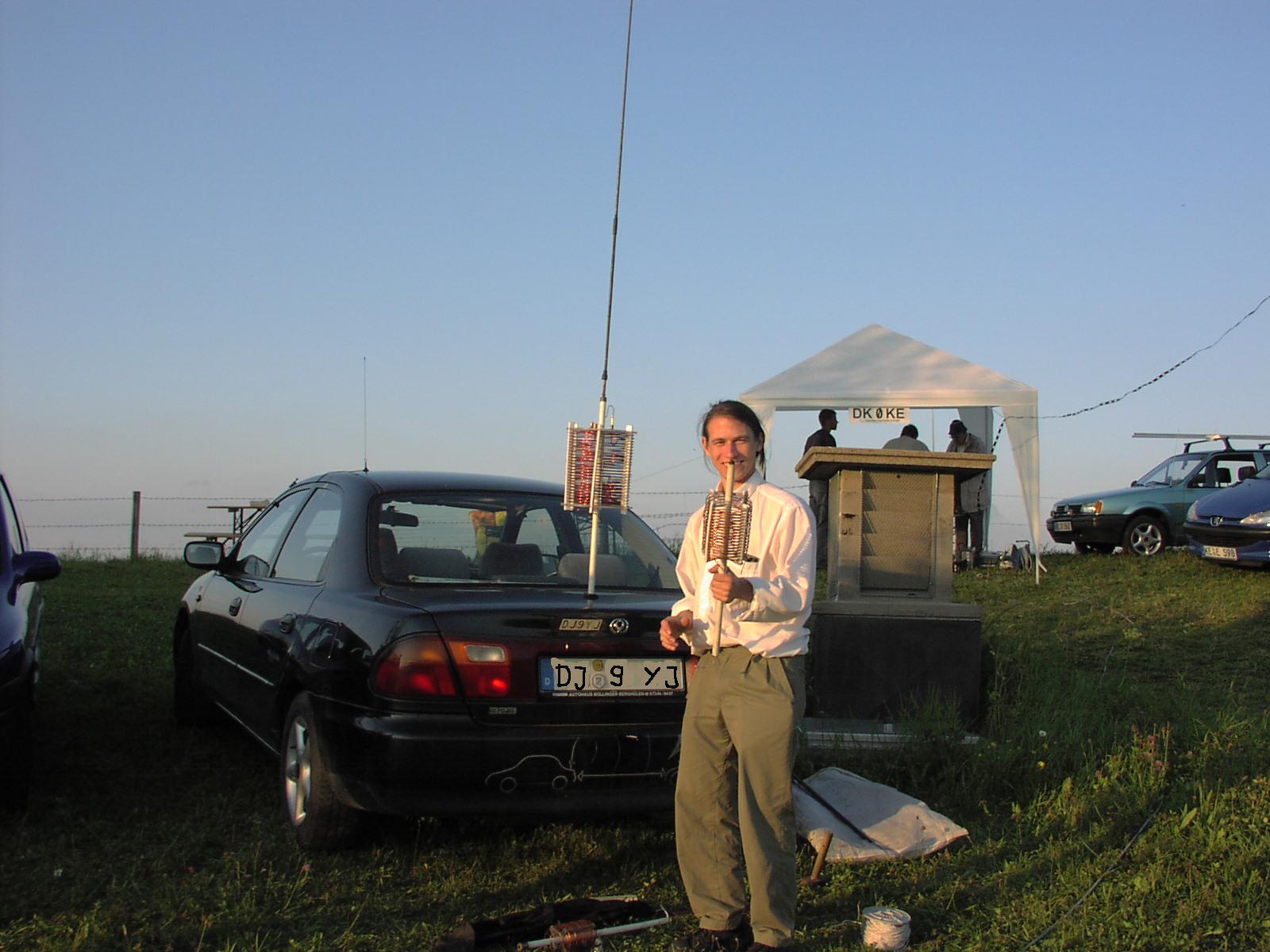
Now the antenna-system looks like this schematic
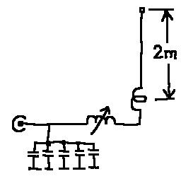
Thats the result

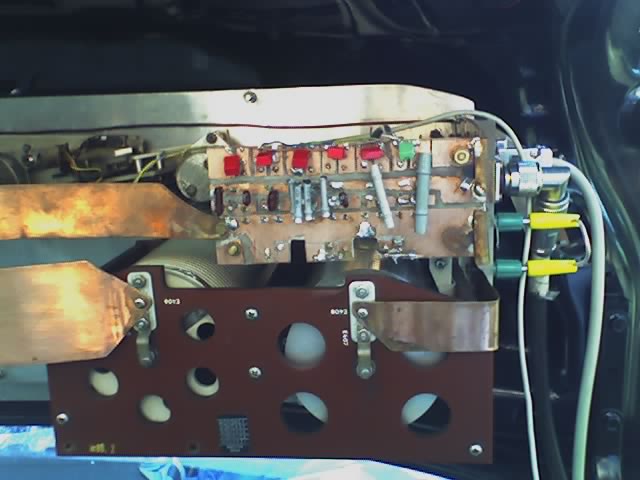
Loading-coil for 160m and 80m